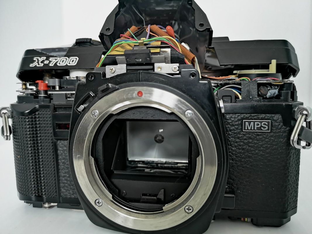
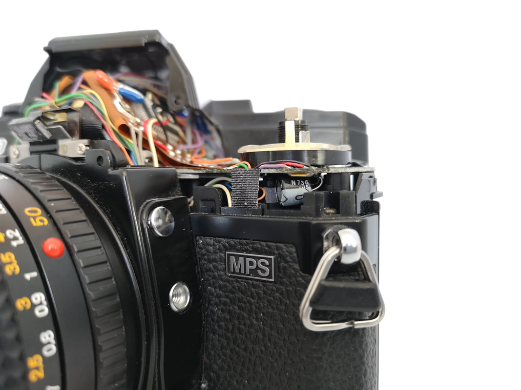
 An X-700 with one of its temperamental release capacitors shown on the far right In the manual focus (MF) era, the XD was arguably Minolta's biggest step forward technologically. It was the first 35mm SLR to feature both aperture- and shutter-priority auto exposure modes and all within the flanks of the first compact Minolta SLR body. The new form factor and added electronic sophistication necessitated the adoption of integrated circuits (ICs) by Minolta. The XD was thus far more complex electronically than its predecessor, the XE, which did have an electronically-controlled shutter and aperture-priority, but was still largely mechanical in its actual operation. The XD's basic electronic layout would prove to be the pattern for all subsequent manual focus Minoltas (including the XG and X-xxx series). And it was the XD that made capacitors front and central in the basic operation of the mirror and shutter assemblies of every succeeding Minolta MF SLR. Capacitor failures are few and far between with XDs and the majority of XGs, but became much more prevalent with the X-xxx series. My personal X-700 fell victim to "capacitor-itis" almost 20 years ago, but my XD 11 has never skipped a beat. That set me to wondering... The Problem Let's start with the problem, work back to its origins, and then look at the solution. Although there are anywhere from 8 to 22 capacitors in any Minolta MF SLR schematic from the XD onward, there is only one (or two at the most) that can be responsible for the most common (READ: not the only) malfunction, which is:
Simply put, (which is the only way to put it, because I am no techie :-), there is not enough electrical power reaching the mirror release electromagnet to allow the camera to go through its entire sequence to fire the shutter. The reason for this? The capacitor responsible for storing sufficient electrical charge to release the mirror is no longer capable of doing so. On the bright side, the fix is simple (although not as easy on the X-700 as the other models, due to the location of its mirror-release capacitor as seen above): replace the failed component(s) and you are back in business. We will get into this procedure later. But, why did this issue become so much more common with the X-700, X-570/-500, X-370/-300, X-7A, X-370n/-300s, X-9, and X-370s models? Basically, it comes down to the quality of the OEM components. The Minolta MF SLRs from the XD forward were all designed from the mid-'70s to the early-'80s. A perusal of the electrical schematics in the service manuals from the introduction of the XD (1977) to that of the X-370/-300 (1984) indicates that they were all designed to use solid tantalum electrolytic capacitors (STECs) for their electromagnetic release circuits. Such capacitors were well-regarded for their very long life and stability, and were in widespread use throughout the electronics industry. However, there was a problem: due to mismanagement of tantalum production in the mid-'70s and the greed of producers, prices for tantalum went through the roof from 1979 - 1980. To that point, STECs were already three to four times as expensive as their main competitors, aluminum liquid electrolytic capacitors (ALECs), but their superior lifespan and stability were worth it to Minolta and other electronics manufacturers. But with the quadrupling of the price of raw tantalum, STECs suddenly became eight to ten times more expensive than their ALEC counterparts. *NOTE* (We will come back to solid vs. liquid electrolytics a bit later :-))
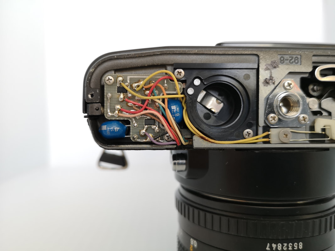
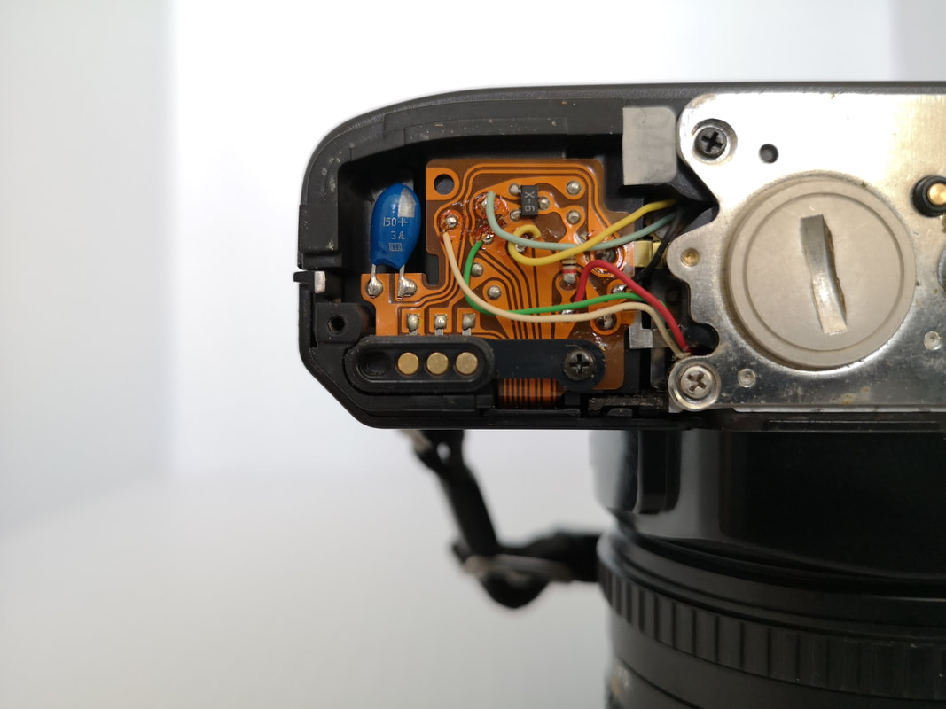
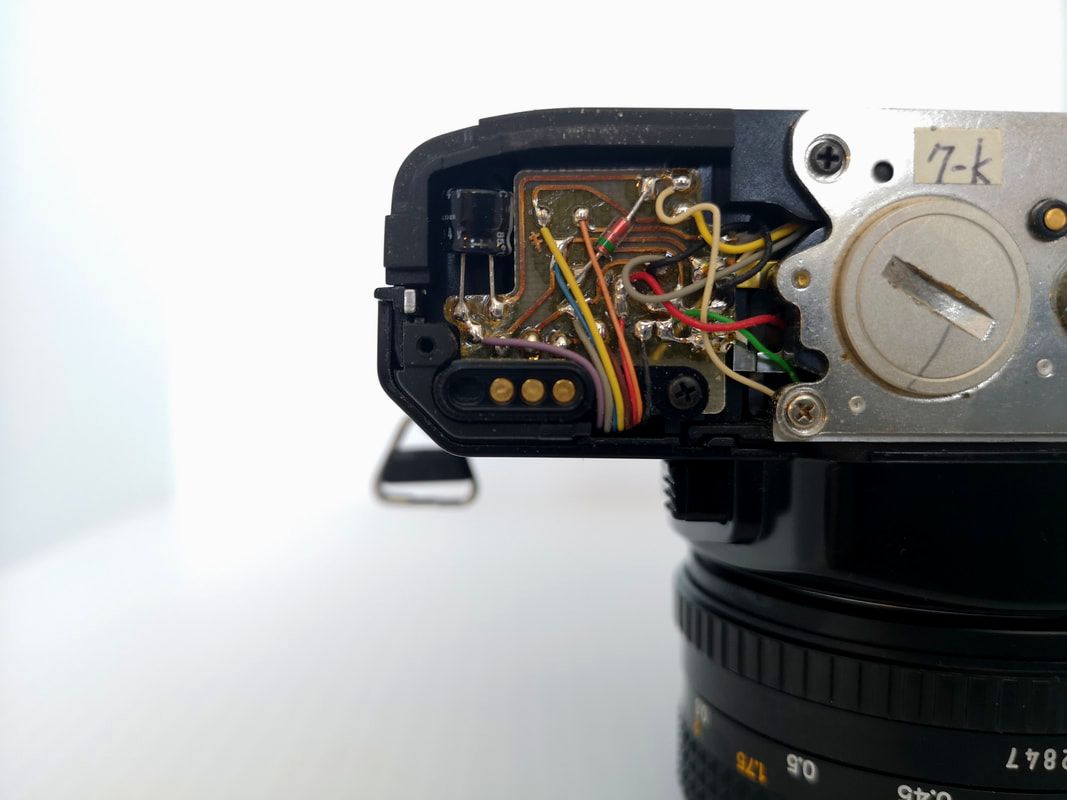
Eventually, tantalum prices did come back down, but ALECs grabbed a pile of market share in the meantime, and the resin-coated radial-type (aka "pearl", referring to their shape) STECs that Minolta used were soon being displaced by the cheaper-to-manufacture chip-style tantalums that were not suitable for cameras. Coinciding with this was the most competitive price war between the Japanese SLR makers yet, as a global recession hit in 1980 and SLR sales began to plummet. With such cost pressures, around 1985 or so, Minolta began to make the switch to ALECs for their release circuits. The general demise of the manual focus SLR, post-1985, also contributed to Minolta's not wanting to invest any more in the quality of X-700 and X-370/-300 (the two remaining MF Minolta bodies) components as they would much rather sell you a shiny new auto focus (AF) SLR and a batch of Alpha/Maxxum lenses to go with it ;-). And there is where the real problem began. After roughly 1,000 hours of powered use owners of ALEC-equipped X-xxx series SLRs could have the dreaded lock-up scenario surface without warning. This could take place at any time from a couple of years to well over a decade, depending on the workload of the camera and whether the ALEC(s) developed a physical leak or not. Even without a heavy workload, just the passage of time has a negative impact on ALECs. The liquid electrolyte slowly degrades from the time of manufacture. So even if the casing of the capacitor remains intact and there are no physical leaks, such capacitors become "leaky" when it comes to their ability to store current. Imagine that the ALEC is like a bucket that you use to carry water from a well to fill a basin some distance away. The bucket has a tiny hole (a leak) in it and every time that you fill it with water, that hole grows slightly bigger. Eventually, it gets to the point where the bucket can no longer hold enough water for the period of time it takes to get from the well to the basin. So how "leaky" are ALECs versus STECs? Well, in the Minolta service manuals the required capacitance ranged from 100 to 150 microFarads (uF) at 3.15V (depending on the model) for the originally specified STECs. Yet, when you come across bodies with ALECs, you find 220uF 4V release capacitors installed from the factory. That was to compensate (somewhat) for the physical process of electrolyte degradation. The problem is that ALECs don't eventually level off, they just keep going to the point of death, whereas the STECs just keep on going (their capacitance loss is on a much smaller scale). This isn't to say that a tantalum capacitor will never fail (every electrical component has a finite lifespan :-)), but you very rarely, if ever, hear of an XD dying as a result of its solid tantalum electrolytic release capacitors. There was no liquid electrolyte to physically leak, evaporate, or otherwise degrade.
It must also be noted that, while the majority of problem bodies were made after 1985 and (the X-700 was produced until 1999 and the final iteration of the X-370, the X-370s, was on sale until early 2005), there is no way of conclusively saying that bodies made between 1980 - 85 as being invariably STEC-equipped. Particularly with the budget-priced XGs was there a greater chance of Minolta having (due to supplier issues or just plain cost, etc.) resorted to ALECs to cut costs. The only way to know for sure is to remove the bottom plate of the camera in question to get a look at the capacitor itself, which is easily done with the assistance of #0 JIS crosspoint (not Phillips) screwdriver. The oblong shape of the STEC vs. the squat cylindrical ALEC will be instantly apparent. Carefully examining the two solder tabs where the release capacitor leads are attached to the board can also give some indication of whether the capacitor has already been replaced at some point. The Solution Fortunately, all of the Minoltas afflicted with "capacitor-itis" can be cured with relative ease and minimal expense if you are reasonably capable with a soldering iron. If you are not comfortable with DIY, there are still independent repair personnel who are willing to do the job for quite reasonable rates often in concert with a general CLA (clean, lube, adjust). If you do decide to DIY, I highly recommend obtaining the specific service manual for the model you are working on (most can be had on PDF for less than $10 USD and some are floating around for free on the web). This is mostly for the troubleshooting section, schematics, and parts lists that will help you to isolate and identify the problem for sure, before you start slinging solder around ;-). A couple of quick tips: 1) the flexible PCBs in these cameras will not tolerate sustained heat, so don't linger with the soldering tip & 2) using a 60/40 or 63/37 Tin/Lead (Sn/Pb) solder (if available to you) will make doing so a lot easier. Components Although resin-coated STECs are quite rare nowadays, we fortunately have had three more decades of development as far as ALECs are concerned and new alternatives such as aluminum polymer capacitors to choose from. For the super-budget-constrained: Nichicon has a 2000-hour @ 85-degree C rated 220uF 4V ALEC (Part# UMA0G221MDD) that can be currently had for $0.35 CAD apiece + shipping from Digi-Key (I just ordered 10 for $0.25/each + shipping). While still an ALEC, it has double the rated lifetime of the standard capacitors in its category. For those who are willing to pay five times as much ($1.50 CAD each or $1.20 CAD each for 10 + shipping) Panasonic's aluminum polymer 150uF 4V capacitor is rated for 3000 hours @ 105 degrees Celsius (Part# 4SEP150M). There are other alternatives out there as far as components and suppliers (Mouser, Farnells, etc.) that may be more convenient for you, this is just FYI :-). Both of these capacitors have the same diameter (6.3mm) as the original 220uF 4V OEM caps with the Nichicon coming in at 5mm long (OEM length) and the Panasonic at 6mm long (still fits). If you somehow get your hands on some STECs, do take care not to install them with reversed polarity. One of the drawbacks of STECs is their inability to handle reversed polarity as well as other types of capacitors (they burn up in a hurry and can cook other components in close proximity). This is another benefit of the service manuals which show the proper polarity in the electrical schematics. Of course, taking a picture of the original cap layout and matching the new cap to it will work just as well (as long as it has not been tampered with before it ended up in your hands ;-). Summary By Model Here are a few details for affected models and recommendations:
Wrap-Up I must say that the whole "Minolta capacitor" story turned out to be more complex and interesting than I had anticipated. I also have hopefully learned a bit about capacitors in the process ;-). Before, I was convinced that it was simply a case of Minolta cheaping out to cut costs, but the whole tantalum saga of the 1970s & '80s opened my eyes a bit. There were some external forces at work, too. Now, I still wish Minolta would have held the line, but I can understand more clearly why they did what they did, especially during the from the mid-'80s onward, when production costs were being cut by everyone. And at least it's a problem that can be fixed quite easily and economically, which is not something you can say about electrical issues with many other vintage SLRs. This article is by no means exhaustive when it comes to electrical problems with these cameras, so I encourage anyone who is seriously looking to diagnose and repair their X-xxx or XG to grab a PDF service manual. It is a worthwhile investment in keeping these very usable and capable cameras going :-). References: Various Minolta Service Manuals for the XD, XG, and X-xxx series of SLRs Multiple Issues of The Bulletin newsletter from 1975 - 94 published by TIC Tantalum capacitor @ Wikipedia
109 Comments
Brenan
4/24/2019 07:15:25 pm
EXTREMELY helpful! Oh my god, this is exactly what I've been looking for, for years now. I appreciate the history and even more so, the technical information and link for the right caps. I am extremely grateful!
C.J. Odenbach
4/25/2019 12:10:45 pm
Good to hear. And thanks for taking the time to comment, Brenan. Hope you can enjoy your Minoltas for a long time yet :-).
Edie
7/31/2019 08:32:55 pm
Wow. Thanks for such an exhaustive run-down and research C.J.! This will doubtless be a hugely useful resource for those of us attempting to revive these cameras.
C.J. Odenbach
7/31/2019 11:43:55 pm
Thank you very much, Edie. That’s what I’m hoping for.
Dragos
9/27/2019 05:24:02 am
I do have this problem, at least this is what i think as the shutter wont fire and when the button is pressed lights are immediately off.
C.J. Odenbach
9/27/2019 09:06:22 am
Hello Dragos,
Dragos
9/27/2019 03:21:03 pm
Thanks, I just replaced the second capacitor...unfortunately still same issue, shutter does not fire. I did not mention that before doing the replacement, the aperture preview lever does not move when push the button on the left side of the mount; the lever is still tension, same for the button; lever can be moved by finger; when push the button, the lever cannot be moved anymore with finger; is this connected to the capacitor or something else is wrong?
C.J. Odenbach
9/27/2019 05:16:15 pm
Hi Dragos, Thank you for uploading this CJ. This DIY camera fix has become important to me recently when my previously flawless fully operational XG-M started to give me trouble. The shutter stopped firing in A mode. It still works with no issues in manual mode (meters properly, shutter fires normally, and film advance works). The meter works in both M and A. But when in A mode, the meter shows up red arrow over 1000s and goes blank when I press the shutter button and of course it will not fire. Since reading your blog I am wondering if you might know if it is only one of the e-caps (hopefully the bottom plate one) that would affect the A mode only function. Other bloggers have indicated the top ecaps could also be the culprit. Can you share any insight on this? I have never held a soldering iron before but the bottom plate one seems doable for me it's the e-caps under the top cover that intimidate me. Thanks for your feedback.
C.J. Odenbach
11/2/2019 08:11:01 am
Hi Stephen,
stephen scibetta
11/2/2019 03:32:00 pm
Yes, I downloaded the service manual yesterday. I noticed my combination of problems in the troubleshooting guide however, I was not sure how to read the schematic (it did look like the issue was in the top section) I guess I will just keep shooting in M mode It's pretty easy to shoot just not as fast. I also own an XG-7 and an X-700, both earlier models manufactured in Japan work flawlessly, I already ordered 10 xg-m ecaps from digikey and a weller soldering iron kit so if you come across any ecap victims in Honolulu please send them my way. As far as I can tell no one is servicing film cameras here. Thank you for your advice. Aloha
C.J. Odenbach
11/2/2019 03:51:15 pm
Thanks Stephen for the update and offering cap services for any Honolulan Minolta users :-). I second your idea to just use M mode, seeing as you have a couple of other options for A mode shooting. Take care and happy shooting with your Minoltas.
Mel Jones
2/25/2020 01:30:20 pm
Like any addict I was sure just one more hit would cure me but it now seems as if I have hung around with addicts too much (thanks CJ) because on top of th SRT and the XD I now have a second XD and along with it an X700 with blown caps. I couldnt resist having a go to get an unloved X700 working. Its sat here right now looking forlorn and waiting for some TLC.
C.J. Odenbach
2/25/2020 02:11:46 pm
Hi Mel,
Mel Jones
2/28/2020 05:14:39 pm
Thanks CJ.
Will
5/24/2020 10:57:56 pm
Hi CJ,
C.J. Odenbach
5/25/2020 12:57:46 am
Hi Will,
Will
5/25/2020 08:48:47 am
Thanks for the quick reply.
David
6/2/2020 03:34:42 pm
Thank you ever so much for posting this incredibly thorough guide! I wanted to report my results in the hopes of further clarifying for others.
C.J. Odenbach
6/2/2020 05:49:32 pm
Thanks for sharing your experience, David. It proves the point that even though tantalums are generally very rugged and long-lived, like any electrical component, they are not infallible ;-).
Mindundi
6/4/2020 10:28:57 am
In my case, Minolta XD: with the shutter armed (after advancing one frame) the LEDs do not light up. When taking the photo and before advancing the film they work normally. Do you know what could be due?
C.J. Odenbach
12/12/2020 09:17:03 am
Sorry for the late reply, Mindundi. Your comment was misfiled. I am sorry I cannot diagnose the problem directly, but there is a free OEM service manual for the XD available at learncamerarepair.com with a Troubleshooting section that may be of assistance. Thanks for reaching out and I apologize again for the delay.
Christian
10/14/2020 04:51:30 pm
Thank you for this comprehensive overview. Unfortunately after Shooting two films this summer with a x700 that was not in use the last 25 years, the exposure times seems to get bad (News batteries and checked with external light meter). While having the third film almost completed, suddenly the camera always shows times far too long. After developing (caffenol - wonderful) I also noticed, that the corresponding Pictures were over-exposed. I opened the upper and lower parts of the body and only found tantal caps. Do you have any suggestions?
C.J. Odenbach
10/14/2020 05:32:58 pm
Thanks for commenting and reaching out, Christian. Unfortunately, the symptoms you are describing are not connected to the release capacitors. It sounds like some other component(s) involved in the meter and/or shutter circuits have failed or are in the process of failing. Sorry that I can’t offer much help other than sending you a PDF copy of the Service Manual, if you would like. Just use the Contact Us page to request it. There is a Troubleshooting section at the end which might help to identify more specifically the cause(s) of the problems you are encountering. Best regards.
Christian
10/15/2020 05:04:50 am
Yes, thank you for the reply. I found the service manual and also a nice page with some additional technical documents (learncamerarepair.com). The condensators (all tantal) in my X700 all look perfect. I'm a bit afraid of the flexibel PCB concerning heat and my soldering iron. The service manual suggests there may be some cold soldering or resistor problems. I guess this will take some time. Good luck I still have a working XD7 that I can use with my Minolta optics.
Hatem Horchani
10/30/2020 03:50:48 am
Very helpful article for even beginners with a clear methodology to explain the problem and providing solutions.
C.J. Odenbach
10/30/2020 07:54:02 am
Thank you for the kind comment, Hatem. I’m a beginner when it comes to electronics so if it’s clear for me hopefully it will be for others, too :-).
C. J. Field
11/6/2020 03:26:57 am
Hi I'm having a problem with my X-700 where both shutter curtains close immediately when the fire button is pressed. If lens is removed and the back taken off when looking at a light I sometimes may or may not see the light through the curtain for a fraction of a second.
C. J. Field
11/6/2020 03:40:42 am
I must also say thank you very much for the super in depth article you have shared.
C.J. Odenbach
11/7/2020 05:55:59 am
Thank you, C.J., for the kind words. Sorry to hear that you’re having an issue with your X-700. It sounds like a problem with the shutter curtain timing rather than a capacitor. If you are feeling like digging into it, I can send you a PDF copy of the Service Manual as it does go into some detail, but shutter repair is not something within my experience so I would recommend taking it to a qualified repair technician. Hope that helps. Best regards.
C. J. Field
11/7/2020 07:34:03 am
Sorry I cannot reply to your comment for some reason.
C.J. Odenbach
12/12/2020 09:37:56 am
Hi C.J., and sorry for the late reply. For some reason I couldn’t reply to you, either. C6 is on the same panel as C4 & C5 that folds over the pentaprism. It is considerably smaller and is at roughly the 7-o’clock position and towards the bottom of the FPC as rendered on the circuit diagram. There are some pointing lines for other components running almost overtop of it that partially obscure it. If you need further help, please use the Contact Us page and I can email you a picture.
Brett Rogers
1/5/2021 07:44:46 am
No questions needing answers, I simply wanted to compliment you on a well written and documented history and repair process, it's excellent work.
C.J. Odenbach
1/5/2021 04:23:05 pm
Thank you very much for the kind words, Brett. And it’s great that you are still enjoying your Minoltas. You made quite the score on the -700 and XD7 :-). Those Acute Matte focusing screens are a boon for aging eyes but you can’t have a complete fleet of Minoltas without at least one SRT ;-). Best regards.
Thomas
1/28/2021 06:54:13 am
Thanks for this guide to capacitorisitis :) , helped to cure my XGM after read through. By chance do you know whether symptoms and cures work too for an X-600. Got one with a dark viewfinder sitting on a desk.
C.J. Odenbach
1/28/2021 08:14:45 am
Hi Thomas,
Alwyn Jones
2/6/2021 08:58:18 am
Wow...great explanation. I'm trying to understand the concept of capacitors and lucky enough to land here. Thanks for sharing the detailed information. Before this I was going through this article https://www.derf.com/how-tantalum-capacitors-work/ but didn't understand much.
C.J. Odenbach
3/18/2021 05:50:44 pm
Thanks, Alwyn. Glad you enjoyed it.
David Simon
2/7/2021 09:09:29 am
Thanks you so much for the above write-up, this is excellent info for the amateur enthusiast. I have a couple of X-700 bodies and one has most certainly suffered a leaked capacitor under the base plate. I have some replacements on order now, hopefully they will get it back up and running again. As for the second body, I have a problem which is most visible in bulb mode, where the second curtain is released at the same time as the first. The second curtain then stops half way and stays there until the shutter button is released, at which point it completes its journey. The issue also seems to be present at any shutter speed. I cant see this specific problem mentioned in the troubleshooting section of the manual, so I wondered of you might be able to point me in the right direction?
C.J. Odenbach
2/7/2021 11:05:54 pm
Thanks, David, for the detailed description of your problem. It is a tough thing to diagnose over the Interwebs and the X-700 Service Manual is not always that helpful. One place you might want to check out is the section on Shutter Charge Adjustment on about p. 96 on a PDF reader. It deals with the amount of shutter overcharge which partially involves the second-curtain stop lever operation. It is possible that the gears may have slipped a tooth or two and that MIGHT be the problem (no guarantees ;-)). If you feel uncomfortable going that deep into the camera, I would recommend taking it to a repair tech. I hope that gives you a place to start, at least, and that you can get both bodies up and running. Best regards.
Ben Upton
3/5/2021 10:28:52 am
Hi C.J.!
C.J. Odenbach
3/5/2021 10:42:42 am
Hi Ben,
Mick Kemsley
3/21/2021 09:28:54 am
I like it but now I am much older the hans/ fingers not so steady
C.J. Odenbach
8/12/2021 07:27:04 am
Glad you liked it, Mick. Take care.
Hi all !
C.J. Odenbach
3/21/2021 04:21:15 pm
Thanks for sharing your experience, Anffray. Salut!
jon laliberte
8/12/2021 12:34:11 am
thank you all for your contributions to this topic. I have been lucky enough to have many operational vintage minoltas over the years. I only have a japan x700 now.
C.J. Odenbach
8/12/2021 07:29:47 am
Thanks Jon. Hope you get many more years of enjoyment with your X-700.
Andy Carlson
8/16/2021 01:33:40 pm
Thanks for this article - it has been very helpful even though I think my X-700 had a different issue... which I will record here in case anyone else has the same problem.
C.J. Odenbach
8/16/2021 01:42:11 pm
Thanks for contributing your experience for the benefit of all, Andy. Hope you get many more miles out of your X-700. Best regards.
Ro
8/29/2021 01:35:22 pm
C.J.
C.J. Odenbach
8/29/2021 02:35:55 pm
Thanks for reaching out, Ro. If the little blue blob is in the far right corner as you look at the camera on its back with the bottom plate removed, it will be a tantalum release capacitor. But I doubt that it is the issue here. If the release capacitor was defective, you would not be able to wind and fire the camera at all. So I suspect something else is at fault. The best I can advise is to download the XG Service Manual from learncamerarepair.com. The troubleshooting section begins on page 169. It takes you through a number of sequences observing the behavior of the LEDs in the finder and other camera functions in both AUTO and Manual modes to narrow down the symptoms, and hopefully, the defect. There is also a circuit diagram on page 75 with the location of the C6 release capacitor clearly shown just for verification purposes. There could be a mechanical or electrical issue with the shutter and/or meter that is the real problem. Please feel free to use the Contact Us page for further communications as the Comments section here doesn't permit a lot of back and forth. I hope that gets you started, Ro. Best regards.
Rogelio Orozco
8/29/2021 04:50:47 pm
Sweet! I've started going through these, but needless to say, I'm a bit overwhelmed. I also have figures out another quirk. The shutter will fire fine when I don't make a lot of contact with my finger, but when I completely cover the finger sensor and press down hard, that's when the shutter hangs.
C.J. Odenbach
8/29/2021 05:37:57 pm
Hi, Ro. You might try cleaning the touch switch with a bit of 99% alcohol or naphtha on a cotton swap and see if that makes any difference. It might be making intermittent contact due to accumulated oils and dirt. 10/1/2021 12:17:13 pm
The same fix worked on my Minolta XG-1!
C.J. Odenbach
10/1/2021 02:16:25 pm
That's great to hear, Daniel. Congratulations on a successful repair!
Melvin
10/24/2021 05:53:05 pm
Is a mint in box XD11 worth the risk of buying as it needs repair?
C.J. Odenbach
10/24/2021 07:01:55 pm
Hi Melvin,
Roland
11/7/2021 05:47:29 am
My X-500 turned off after one-three shots and had a blinking "A" in the viewfinder. I thought that it was batteries problem and put batteries from X-500 into XG-2 which worked fine. I also swapped them with batteries from my X-700 and the issue hasn't gone away. At this point I thought that I might swap capacitors between X-500 and XG-2. I did that and nothing changed neither in X-500 nor in XG-2.
C.J. Odenbach
11/7/2021 07:15:15 am
That's a great question, Roland. And it highlights an important difference between the XGs and X-xxx series. The XG-2 has a minimum voltage threshold of 1.75 - 2.15V whereas the X-300, -500, and -700 all have a minimum threshold of 2.46 - 2.56V. That 0.3 - 0.7V difference explains why your XG-2 goes merrily on its way with weaker batteries. According to Minolta, for a single LR-44 or SR-44 cell to be considered "normal", it must be producing at least 1.4V for a total of at least 2.8V with two cells. Being alkalines, LR-44s begin to drop voltage almost immediately from installation and steadily continue to drop compared to the silver oxide SR-44s, which have a flatter discharge curve. They thus cross the minimum voltage threshold much sooner than SR-44s.
Seth
12/19/2021 01:25:39 am
do these suspect caps on the XD models also account for the common failure of the shutter speeds all ending up the same? I don't mean the shutter lag with the air piston that needs cleaning, I mean when the camera's speed selection sounds the same down to 1 second.
C.J. Odenbach
12/19/2021 01:57:38 am
Hello Seth. The release capacitors do not affect the timing of shutter speeds. The are only responsible for initiating the exposure sequence beginning with the mirror flip. Shutter speeds are controlled by IC1 (Integrated Circuit 1) in concert with the shutter assembly itself and other switches and contacts. There is a Trouble Shooting section in the XD Service Manual that is available for free at learncamerarepair.com that may be able to help you narrow the problem down. If the problem occurs in all modes and at all speed settings, including the mechanical settings of O, X, and B, it is likely that the shutter assembly itself is the problem. If it only occurs in one or two of the A, S, or M exposure modes, but not all three, then there could be a defect in IC1, a switch, or another electronic component named in the flow chart on pages 12-13 of the troubleshooting section. I hope that helps to get you started in tracking the problem down. Best regards.
Will
1/16/2022 01:34:48 pm
Thanks for the great article and advice.
Will
1/16/2022 01:38:23 pm
I also forgot to mention - my brother removed some film so the rewind button on the bottom camera is still depressed - I was wondering if had to do with the winding mechanism still being jammed? Thanks again!
C.J. Odenbach
1/16/2022 02:03:49 pm
Hi Will,
Will
1/18/2022 10:32:48 am
Thanks for your reply CJ.
C.J. Odenbach
1/18/2022 10:53:18 am
Hi Will,
Jack
3/1/2022 12:29:42 pm
Hi,
C.J. Odenbach
3/1/2022 01:09:06 pm
Thanks for reaching out, Jack. You will be fine with your 150 uF caps. The reason Minolta selected 220 uF instead of 150 uF when they switched to the aluminum electrolytics was to try and mitigate the characteristic of such capacitors to lose capacitance over time versus the negligible degradation of the original 150 uF tantalums that came in the earliest X-370 units (such as the one pictured in the article). That gave them a 70 uF buffer that would gradually shrink as the electrolyte degraded. Once their supply of 150 uF tantalums was exhausted, Minolta simply switched to the cheaper 220 uF aluminum electrolytics. If they had started out with 150 uF ALECs, the caps would have failed much sooner than was acceptable.
Jack
3/1/2022 02:13:59 pm
That was the answer I was looking for but it also makes complete sense. I went a head and replaced it and the shutter fires! Fully functional. Thanks, take care.
C.J. Odenbach
3/1/2022 02:22:09 pm
Excellent to hear! Enjoy!
Sergio
3/31/2022 10:32:08 am
Hi, C.J.
C.J. Odenbach
3/31/2022 11:37:20 am
Hi Sergio.
Sergio
4/1/2022 08:47:37 am
Oh, C.J... But I love you! Thanks so much! ^_^
Hiki Bennett
4/2/2022 04:46:01 am
G’day from NZ I’ve got a x570 with what appears to be a buggered cap, I tried replacing with 100uf 4v cap but it still does not work?
C.J. Odenbach
4/2/2022 07:11:40 am
G'day Hiki,
Hiki
4/20/2022 11:37:56 pm
Cheers Colin,
C.J. Odenbach
4/21/2022 12:25:57 am
Hi Hiki,
Andy k
4/22/2022 10:09:23 pm
Wow good to see some love being spread for the X-xxx series , i bought my x700 new in japan
C.J. Odenbach
4/22/2022 11:16:24 pm
Hi Andy,
Peter Bölke
7/11/2022 01:02:37 am
Hi,
C.J. Odenbach
7/11/2022 08:20:58 am
Hi Peter,
Peter Bölke
7/11/2022 10:33:46 pm
Hi C.J.
C.J. Odenbach
7/11/2022 10:41:14 pm
Hi Peter,
Sab
7/11/2022 10:17:00 am
Hello C.J.,
C.J. Odenbach
7/11/2022 08:56:52 pm
Hi Sab,
Sab
9/21/2022 11:43:47 am
Hi C.J.,
C.J. Odenbach
9/21/2022 12:23:45 pm
That's great to hear, Sab. Congratulations on a successful repair. I know what you mean about the trepidation of a soldering job on one's own camera ;-). Hope you can enjoy your XD7 for a long while yet. Best regards.
John
1/17/2023 10:21:46 am
This post and the comment section are pure gold! However, I have a really weird problem with my X-300 so if anyone can think of a solution, I would be really grateful. 2 films ago I had a problem with rewinding. It's like that button underneath for releasing the whole winding mechanism didn't work at first so I could have put too much pressure into trying to rewind before I realised something was stuck and pushed the button again and then it worked normally. But the next film I shot was completely fine. And rewinding was fine. But when I put another film after that, the shutter count and that count that tells you how much film you've used didn't work at all. They were just stuck to S. I've shot the film ignoring that but half of the photos were completely unexposed and on the other half were exposed only on the right side while the left half was black. Then I tried a few times to click the shutter without the film but the advance lever got stuck. I opened the bottom and saw that one small lever beneath the big metal "wheel" is in the way of that mechanism and realised if I advance the lever and release it gently, it will get stuck, but if I release advance lever suddenly, it will be ok. BTW, capacitor looks ok and has the same Voltage reading as batteries.
C.J. Odenbach
1/17/2023 11:14:45 am
Hello John,
John
1/19/2023 04:44:38 am
I really appreciate this! Upon further investigation I also came to realize that shutter curtain is only opening one third on the left side. I've found a local repairman who upon hearing about the problem said that he could fix it for roughly 132 Canadian Dollars but since I could actually buy another X-300 within that price point, I'll give it a try with figuring out this manual.
C.J. Odenbach
1/19/2023 07:33:45 am
You are welcome, John. That is one of the quandaries of vintage cameras: when to repair or when to replace? If the technician is good, a repair can be worth it, as you will have a camera that has been more thoroughly checked over than almost any new-to-you copy. And if they offer a decent warranty, you may be further ahead than starting all over again. Totally up to you. Take care.
Nathan
3/14/2023 10:06:36 pm
Hi there,
C.J. Odenbach
3/14/2023 10:11:46 pm
Hi Nathan,
Andy Carlson
8/14/2023 03:32:56 pm
Second Minolta back to life. This one is a US bought XG-M circa 1982 that belonged to my late Aunt. In fact it was the reason I bought a Minolta once I'd started to earn. I was surprised and pleased to find it while sorting through my Aunt's posessions. After replacing the batteries I found that it had the classic capacitor symptoms.
C.J. Odenbach
8/14/2023 04:49:13 pm
Nice to hear from you again, Andy. And congrats on a second successful resuscitation :-). The polarity of the capacitors in your cameras both match the service manuals (negative on the inside and positive towards the outside of the body. It definitely pays to doublecheck and follow the manual or the previous installation, if it was OEM.
Paul
2/15/2024 08:18:18 am
Hi, I've acquired an X-9 which is completely dead. I've removed the bottom plate and it looks like the cap has blown. There is green corrosion where it is soldered to the board. My question is, after searching the internet, is the polarity of the cap. Is it negative inboard as mentioned above for this camera. Kind regards.
C.J. Odenbach
2/15/2024 08:50:14 am
Hello Paul. Very good question to ask. The X-370 Service Manual (which also covers the X-9, X-300, X-7A, & X-500/-570)) shows the OPPOSITE polarity for the release capacitor to the X-700 and XG-M models covered in previous comments. So, for the X-9 it is POSITIVE INBOARD and negative outboard for the C7 capacitor. This is a perfect example of why it pays to check for each model rather than just assuming they are all the same. Best wishes on a successful repair.
Mr Paul Croft
2/20/2024 02:09:16 pm
Thank you for your quick reply, I'm glad I asked now.
C.J. Odenbach
2/20/2024 03:39:14 pm
You're very welcome, Paul. Best regards.
Nick
3/7/2024 05:14:43 am
Amazing info thanks!
C.J. Odenbach
3/7/2024 08:55:29 am
Hello Nick. Thanks for commenting.
Max
5/27/2024 07:44:58 am
Hi, thanks a lot for this detailed research! Came here cause I got an XG-1 (the old model) at a thrift store with the advance lever stuck-mirror up- won't fire problem. Great I thought, it'll be the capacitor, so I opened the bottom plate and.. nothing! No circuit at the place where the other models have one. Picture: https://drive.google.com/file/d/1kq1waZ0D1CE6PPgkDP061SDUl7V8TVQ6/view?usp=sharing
C.J. Odenbach
5/27/2024 08:14:27 am
Hi Max. Thanks for commenting. Unfortunately, if there is no flexible circuit in the bottom location, it sounds like someone has been into the camera previously and removed it. There should be a large integrated circuit chip (IC4 on the schematic) with 12 pins (6 on each side) and the release capacitor (C6 on the schematic) beside it towards the outside of the camera (the + lead should be toward the outside of the camera). Minolta grouped both the old (XG-1) and newer XG-1(n) models, along with the XG-A in the same service manual, so circuit differences appear to be minimal. If you would like, please use the CONTACT page to email me and I can send you a picture of what the bottom flexible printed circuit should look like on an original XG-1 for comparison with yours. Best regards
Max
5/27/2024 03:12:19 pm
Thanks, will do!
Ian C
6/22/2024 05:13:04 am
Just a note to say thanks for a very interesting and informative article. Happy to find this as starting to revive my Minolta film camera experience.
C.J. Odenbach
6/22/2024 06:45:52 pm
Thanks for taking the time and for the kind comment, Ian. Best wishes on your return to Minolta :-).
Jack Huang
7/6/2024 10:41:03 am
Hello! Thanks for the detailed information.
C.J. Odenbach
7/8/2024 08:26:44 am
Hello Jack, Your comment will be posted after it is approved.
Leave a Reply. |
C.J. OdenbachSuffers from a quarter-century and counting film and manual focus SLR addiction. Has recently expanded into 1980's AF point and shoots, and (gack!) '90s SLRs. He even mixes in some digital. Definitely a sick man. Categories
All
Archives
June 2024
|
 RSS Feed